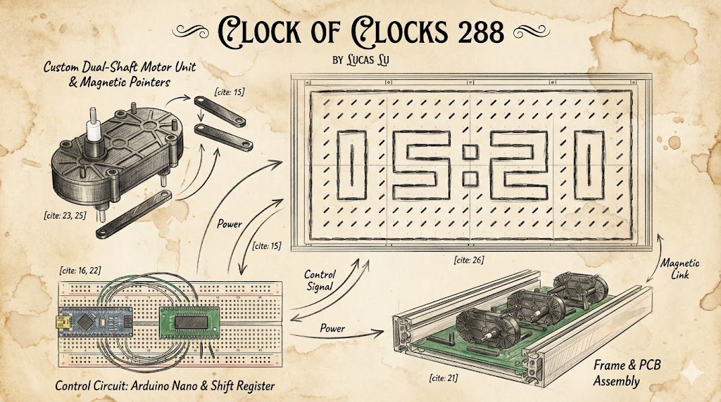
Clock of Clocks 288
Conceptual Design
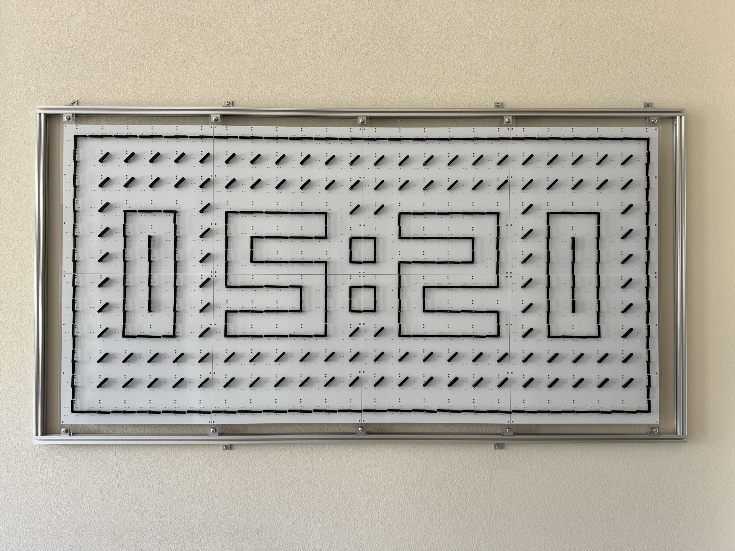
Final Construction
The Inspiration
When I first encountered the A Million Times clock, I was instantly captivated. Hundreds of independent hands dancing in perfect synchronization to form digits and waves—it felt like watching mechanical magic. However, the premium price tag was a significant barrier. Driven by curiosity and a “maker” spirit, I decided to build my own 24 x 12 matrix version from scratch.
System Architecture
This massive kinetic installation is powered by a distributed control network of 73 microcontrollers:
- Master (Arduino Mega): The brain. It connects to NTP servers via WiFi to fetch precise time and maps it onto a 12×24 coordinate system. It manages 9 distinct animation patterns (Waves, Rectangles, Random patterns) and dispatches target positions to 72 slave nodes over the I2C bus.
- Slaves (72x Arduino Nano): The muscle. Each Nano acts as an I2C slave node, controlling 4 dual-shaft stepper motors (8 independent hands per node). They handle high-frequency step generation and real-time sensor monitoring.
Engineering Breakthrough: Closed-Loop Calibration
To solve this, I integrated a Hall Effect Sensor Matrix into the custom PCB. Each clock hand contains a tiny neodymium magnet, and two Hall sensors are positioned along its rotation path.
My V2.0 firmware implements a “Silent Calibration” logic: instead of a clunky global reset, the Arduino Nano monitors the exact moment the magnet passes the sensor. By calculating the average trigger position, the system determines the position_diff. If an error exceeding 2 degrees is detected, the slave node automatically compensates for the drift during its next movement, ensuring the array remains perfectly aligned 24/7.
Open Source & Code
This project is fully open-sourced for the geek community. Below are snippets of the logic managing the distributed time distribution and the real-time sensor feedback.